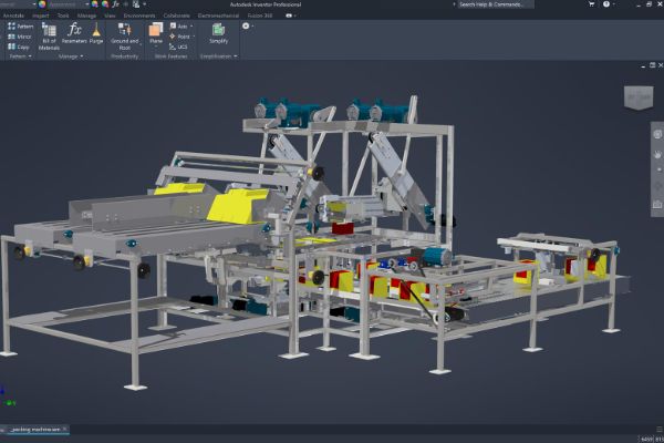
Inventor Advanced – Simulation

Learn the fundamental principles and recommended workflows for simulations of mechanisms using Autodesk
Prototypes by simulating the operation of mechanisms and motorized assemblies, parts and assemblies, perform parametric design representing real-world, industry-specific design scenarios.
PREREQUISITES
Has Finite Element Analysis (FEA) knowledge, can interpret results.
TARGET GROUP
Engineer or Designer who involve in visual simulation by using Autodesk
Duration
3 Days (21 hours)
Course Achievement
Certificate of Completion by Autodesk
At the end of the course, you will be able to:
- Activate and navigate the Autodesk Inventor Professional Simulation environment to conduct FEA analyzes.
- Create, edit, and assign idealizations and materials (linear, nonlinear, and composites).
- Manage the creation, setup, and modification of analyses and subcases that are used to analyze both static and dynamic model.
- Create constraints with the required degrees of freedom and assign them to entities.
- Create loads that accurately represent the magnitude and location of the loads the model will experience in the working environment.
- Create Surface Contact elements to define contact between interacting components.
- Assign global and local mesh settings.
- Review and create result plots for analyzing the results.

BENEFITS OF Inventor Advanced – Simulation TRAINING

Enhanced Design Validation

Faster Time-to-Market

Increased Product Safety

Deeper Understanding of Engineering Concepts
View Course Content
DAY 1
CHAPTER 1: PARTS MODAL AND STRESS ANALYSIS
- Simulation 1: About this tutorial
- Open the Model for Modal Analysis
- Enter the Stress Analysis Environment
- Assign Material
- Add Constraints
- Preview Mesh
- Run Simulation
- View the Results
- Summary
- Simulation 2: About this tutorial
- Copy Simulation
- Create Parametric Geometry
- Include Optimization Criteria
- Add Loads
- Set Convergence
- Run Simulation
- View the Results
- Summary
CHAPTER 2: ASSEMBLY STRESS ANALYSIS
- About this tutorial
- Get Started
- Stress Analysis Environment
- Excluding Component
- Assign Materials
- Add Constraints and Loads
- Stress Analysis Settings
- Contact Conditions
- Generate Mesher
- Run the Simulation
- View and Interpret the Results
- Summary
CHAPTER 3: CONTACTS AND MESH REFINEMENT
- About this tutorial
- Open the Model
- Stress Analysis Environment
- Create a Simulation
- Exclude Components
- Assign Materials
- Add Constraints and Loads
- Define Contact Conditions
- Specify and Preview Meshes
- Run the Simulation
- View and Interpret the Results
- Copy and Modify Simulation
- Specify Local Mesh Controls
- Run the Simulation Again
- View and Interpret the Results Again
CHAPTER 4: ASSEMBLY MODAL ANALYSIS
- About this Tutorial
- Open the Assembly
- Create a Simulation Study
- Exclude Components
- Assign Materials
- Add Constraints
- Create Manual Contacts
- Specify Mesh Options
- Preview Mesh and Run Simulations
- View and Interpret Results
- Summary
CHAPTER 5: FEA ASSEMBLY OPTIMIZATION
- About this Tutorial
- Open the Assembly
- Define the Simulation
- Assign Material
- Adding Constraints
- Adding Loads
- Modify the Mesh
- Preview the Mesh
- Create parametric Geometry
- Optimization Criteria
- Run the Simulation
- View and Interpret the Results
- View and animate 3D plots
- View XY Plots
DAY 2
CHAPTER 6: STRESS ANALYSIS CONTACTS
- About this Tutorial
- Overview
- Open the Assembly
- How a Caulk Gun Works
- Assembly Simulation
- Contact Types
- Bonded Contact
- Separation Contact
- Sliding and No Separation Contact
- Separation and No Sliding Contact
- Shrink Fit and No Sliding Contact
- Spring Contact
- Loads and Constraints
- Simulation Results
CHAPTER 7: FRAME ANALYSIS
- About this Tutorial
- Open the Assembly
- Frame Analysis Environment]
- Frame Analysis Settings
- Assign Materials
- Change Beam Properties
- Change Direction of Gravity
- Add Constraints
- Add Constraints to the Next Beam
- Add Loads
- Run the Simulation
- View and Interpret Results
CHAPTER 8: FRAME ANALYSIS RESULTS
- About this Tutorial
- Get Started
- Frame Analysis Environment
- View and Interpret the Results
- Display Maximum and Minimum Values
- View Beam Detail
- Display and Edit Diagram
- Adjust Displacement Display
- Animate the Results
- Generate Report
CHAPTER 9: FRAME ANALYSIS CONNECTIONS
- About this Tutorial
- Connections Overview
- Open the Assembly
- Frame Analysis Environment
- Change Directions of Gravity
- Add Custom Nodes
- Add Custom Nodes
- Change Color of Custom Nodes
- Assign Rigid Links
- Add Constraints
- Run the Simulation
- View the Results
- Assign a Release
- Run the Simulation Again
- View the Updated Results
CHAPTER 10: MODAL TYPE OF FRAME ANALYSIS
- About this Tutorial
- Open the Assembly
- Frame Analysis Environment
- Create a Simulation Study
- Run the Simulation
- View the Results
- Animate the Results
DAY 3
CHAPTER 11: DYNAMIC SIMULATION
- About this Tutorial
- Open the Assembly
- Degrees of Freedom
- Automatic Constraint Conversion
- Assembly Constraints
- Add a Rolling Joint
- Building a 2D Contact
- Add Spring, Damper, and Jack Joint
- Define Gravity
- Impose Motion on a Joint
- Run a Simulation
- Using the Output Grapher
- Simulation Player
CHAPTER 12: DYNAMIC SIMULATION PART 2
- About this Tutorial
- Work in the Simulation Environment
- Construct the Operating Conditions
- Add Friction
- Add a Sliding Joint
- Use the Input Grapher
- Use the Output Grapher
- Export to FEA
- Publish Output in Inventor Studio
CHAPTER 13: ASSEMBLY MOTION AND LOADS
- About this Tutorial
- Open Assembly
- Activate Dynamic Simulation
- Automatic Joint Creation
- Define Gravity
- Insert a Spring
- Define Spring Properties
- Run the Simulation
- Insert a Contact Joint
- Edit the Joint Properties
- Add Imposed Motion
- View the Simulation Results
- View the Simulation Results (continued)
- Export the Data
CHAPTER 14: FEA USING MOTION LOADS
- About this tutorial
- Open Assembly File
- Run a Simulation
- Generate Time Steps
- Export to Stress Analysis
- Use the Motion Loads in Stress Analysis
- Generate a report

